Tuesday, March 15, 2011

Week 7 (S1"11)

The Darlington Transistor Array
 
For more compact version of the Darlington pair transistor you could use the Texas Instrument ULN2803A which is contain 8 Darlington pair transistors with has build in 2K7 base resistor and clamp diode for each Darlington pair transistors. This makes this Darlington transistor array suitable for driving the relay or motor up to 500mA (this is a maximum datasheet value) directly from the microcontroller output.


To increase the output current up to 1 A (2 x 500mA, remember this is a maximum datasheet value, for practical application use just half or 2 x 250 mA) you could simply use two Darlington transistor array connected in parallel, the following is the sample circuit for driving two DC motors using the ULN2803A Darlington transistor array:


 Thanks to the build in internal 2K7 base resistor and the two clamp diode, you don’t need any external component when using ULN2803A to drive the DC motor from your microcontroller port. The Darlington transistor array ULN2803A could be used to drive up to 50 volt voltage load.

Wednesday, March 2, 2011

Week 6 (S1"11)


Design IR sensor circuit by using Express PCB software


Tuesday, March 1, 2011

Week 5 (S1"11)


Development Of High-speed Miniature Mobile Robot For Soccer


 Top View

Bottom View

Front View

Rear View

Infrared Sensor Component

Top View with Microcontroller
Line Sensor LSS05 Interfacing with Microcontroller
Calibration Line Sensor


Infrared Sensor Circuit (Top View)

Infrared Sensor Circuit ( Bottom View)

Sunday, February 20, 2011

Week 4 (S1"11)


Tamiya Ball Castor
Description
  • 12mm diameter
  • Selectable height (25mm and 35mm)
  • Plastic casing
  • Light application
  • Comes in 2pcs/set

  • Line Sensor (LSS05)
    Descriptions: This newly developed Auto-calibrating line sensor is super easy to use. Come with 5 pairs of IR transmitter and receiver, it can covers line detection of 1cm to 3cm wide, dark color or bright color line. With 1 press, it will start "recognizing" the surface under it, calibrating the threshold between dark and bright. it takes 4 to 5 seconds only. After that, it is done, being stored in internal non volatile memory, it will still "recognize" the line even after power off and on again. Come with connector and wires.

    Features:
    • 5V power
    • 5 digital output reprsenting logic of 5 IR sensor
    • 1 press to start calibration
    • 2 press to toggle logic into Dark On mode, to sense dark line
    • 3 press to toggle logic into Bright On mode, to sense bright line
    • Calibration button for easy of calibration
    • Combine with MC40A for line following robot development


    LSS05  (Low cost  line sensor bar) consists of 5  IR  transmitter and  IR  receiver pairs. LSS05 is the typically used for embedded system or robots in line following task. LSS05 can be used for either dark or bright line following. Any color with distinct brightness difference is suitable for LSS05.

    The IR transmitters on LSS05 are pulsed to allow the transmitter to off at certain idle period of sensor. This is to minimize the current consumption of LSS05 to at least half of the current  consumption  compared  to  a  normal  unregulated  IR  line  sensor.  Power  polarity protection is available on LSS05 in case the user accidently applies a reverse voltage. 

     LSS05  have  5  digital  outputs  to  user  indicating  the  existence  of  the  line.  The threshold  to  the brightness of  line existence will be set when  the user calibrate the sensor  to the surface that it will recognize. One digital input of calibration signal is available to user for automated calibration  function by  the user system. User can pull down  this signal  line with microcontroller  to  calibrate  the  sensors.  This  signal  line  also  can  be  use  to  enter  different mode of LSS05. Each  sensor of  the 5  sensors on LSS05  is  independent of  each other. The refreshing  rate  of  the  sensors  is more  than  100Hz.  Every  sensor  is  provided with  its  own LEDs as indication of line detection. 

    LSS05  has  a  manual  calibration  button.  The  calibration  button  is  multifunctional. User can enter different mode of functions using calibration button  too as  the alternative  to the calibration signal.   
      

    A – Sensor indicator LEDs (red) will light up showing that it detects line. 

    B – Calibration button  is used  to  enter different modes. Press once  to  enter  the calibration mode. Press twice to set the line sensor bar into dark line following mode and press 3 times to set the line sensor bar into bright line mode.

    C – Mode indicator LED (orange) is for indication of the mode. LED will light up if LSS05 is in bright line detection mode. Otherwise, it is off. 

    D – PIC16F819 PIC microcontroller for data processing.

    E – Power and output signal connector

    F – Power indicator LED (green) showing the board is supplied with power. Maximum input power is 5V.
      
     A – Pairs of IR sensor which consist IR transmitter and IR receiver.

    B – It is reserved for Manufacturing Test Point. Please DO NOT short or connect wire to any of these pins.

    C –Input/output signal label showing the Power (5V, GND), output signal pins (O1-O5) and calibration signal (Cal.).  
     
    LSS05 cable connector

    Figure below shown cable used to connect LSS05 to microcontroller. 2020H-08 connector is used at the end of the cable.
     
    Pin pitch for 2020H connector  is not standard size for donut board pin pitch. To use LSS05 with donut board, simply cut  the end of connector and solder another  type of connector  like 2510  or  3960  connector. Following  figure  is  showing  the  step  to  connect LSS05  to  others type of connector.


    Figure below shown LSS05 was connected to donut board.  

    GETTING STARTED

    LSS05 need to be calibrated to retrieve the dark and bright value of the surface that it will do the line follow. Every of the IR sensor pairs need to be exposed to the dark and bright surface  for  it  to  read  the value  and  save  it. LSS05 will  save  the value  in EEPROM,  it will retrieve  back  the  data  from  the  EEPROM  every  time  its  switch  on. Hence,  only  one  time calibration  is  needed  for  the  same  surface  and  line.  To  calibrate  LSS05,  simply  press  the calibration push button once or pulling down  the Cal. for few milliseconds. Calibration will be start by exposing the sensor to the bright surface and then to the dark surface as indicated by the LEDs. 3 LEDs blinking means the bright calibration (2.5 seconds) and 2 LED blinking means  the  dark  calibration  (2.5  seconds).   Calibration  is  normally  done  by  crossing  every sensor across  the line  that  it will follow as shown  in  the figure below. Sensors will save  the brightest value  in  the bright  calibration process  and darkest value  in dark  calibration. User can  calibrate by  simply  swinging  the  sensors  across  the dark and bright  surface  in order  to expose  every  sensor  to  the  dark  and  bright  surface.    Calibration  of  every  sensor  is independent and value of each sensor will be saved.

    Example motions of calibration by crossing the sensor between the lines.  

     1. Calibration button and signal.
     
    The calibration button or the calibration signal (Cal.) has 2 functions. The 1st function is to call for calibration of the line sensor and the 2nd function is to set whether the sensor bar will operate for dark line following or bright line following.  

    2. Using the calibration push button

    Press the push button once to set the sensor bar into calibration mode. LSS05 will go into calibration mode and the red LEDs will start blinking accordingly to  indicate whether it is calibrating for dark color or bright color. 

    Press the push button twice will set the line sensor into dark line following mode which LSS05 will detect dark line. Sensor indicator LEDs will light up if it detects dark surface (the line is dark).

    Press  the push button 3  times will  set  the  line  sensor bar  into bright  line  following mode which LSS05 will detect bright  line;  sensor  indicator LEDs will  light up  if  it detects bright surface (the line is bright). Dark/Bright indicator (D/B) indicator LED will light up in orange color for this mode. 

    3. Using the calibration signal

    The calibration signal  from  the sensor connector can be used  to perform exactly  the same  function  as  the  calibration  push  button.  The  calibration  signal  line  requires  user  to generate falling edges to set for appropriate mode.  LSS05 detect how many falling edges to set to appropriate mode.

    •  One falling edge pulse for calibration mode as shown in figure below. After the falling edge pulse the sensor will start calibration.

    •  Two falling edges for setting the LSS05 into dark line mode. The 2 falling edges need to be in range of 1.5 seconds.

    •  3 falling edges for setting the LSS05 into dark line mode. The 3 falling edges need to
    be in range of 1.5 seconds. 
     

    *Reminder: Please keep the Cal. signal at high logic level 5V if it’s not generating pulse for the function of the signal.


Thursday, February 17, 2011

Week 3 (S1"11)


Mini Wheel 46x10 mm  

This custom-designed plastic wheel has a rubber tire measuring 46mm in diameter and is designed to fit the output shafts on our SPG10 series gearmotors as well as the Solarbotic metal gear motor.

Specification:

  • Diameter : 46mm
  • Width of tire: 10mm
  • weight: 12g
XBee 1mW Wire Antenna 
Description
Finally user can enjoy another simple yet reliable wireless communication for robots. XBee OEM RF module has been used in many robotics applications world wide to offer wireless communication, point to point and also mesh network. No more searching for surrounding device and request for connection, it can send data wireless after powering up without any extra configuration. Additionally, the communication range is very good (100 meters) for a low powered device (1mW). Its small form factor saves valuable board space. No configuration is necessary for out-of-box RF communications. XBee module comes with application software to ease user in editing configuration and also for functional testing. Since the XBee module pin is 2mm pitch to pitch (is difficult to plug in standard board), you can use SKXBEE as starter kit.

Product Summary:
  • ISM 2.4 GHz operating frequency
  • 1 mW (0 dBm) power output
  • Industrial temperature rating (-40° C to 85° C)
  • Indoor/Urban range: up to 100 ft (30 m)
  • Outdoor/RF line-of-sight range: up to 300 ft (100m)
  • Interface data rate: Up to 115.2 Kbps
  • Receive current: 50 mA (@ 3.3 V)
  • Transmit current: 45mA (@3.3V)
  • 6 10-bit ADC input pins
  • 8 digital IO pins
  • AT or API command set
  • Power-down sleep current: <10 µA
  • Supply voltage: 2.8 - 3.4V
  • 2mm pitch to pitch DIP pin
Package included:
Dimension:  2.438cm x 2.761cm

XBEE STARTER KIT 
Description
XBee has becoming extremely popular among robot builder and embedded wireless communication. It can be use for control and monitoring, data streaming, real time wireless update and also wireless downloader.Finally user can enjoy another simple yet reliable wireless communication for robots. However, using XBee OEMRF module need extra work to interface since it is 3.3V power and offer 3.3V interface. With these reason, Cytron Technologies has designed Starter kit for user to easily use XBee module. With SKXbee, useronly requires 4 simple wiring to offer wireless communication to 5V microcontroller. On board USB interface, can easily turn SKXBee into XBee dongle.

Features:
  • Communication range up to 100 meters
  • Soldered with XBee module and tested before being shipped
  • USB Plug and Play UART function
  • 5V powered
  • 5V UART interface, ready for microcontroller interface
  • Default baud rate of 9600bps
  • Long Range Data Integrity
  • Low power consumption
  • Compact yet easy and reliable platform
  • As serial port replacement (wireless)
  • Point-to-point, point-to-multipoint and peer-to-peer topologies supported
Dimension: 8cm x 4cm
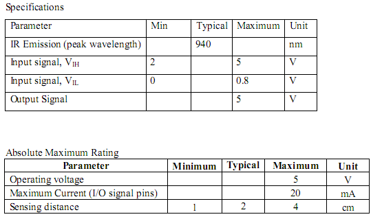
IR Sensor Set 
Description
The IRS-01 IR sensor set consists of an IR transmitter and an IR receiver mounted side by side on a tiny PCB. With a 5 VDC power, it can be used as a reflective type IR sensor for mobile robot or any simple control system.

Dimension: 1.2cm x 1cm


Sharp Analog Distance Sensor (10-80cm)


Description:

The Sharp distance sensor is a popular choice for application and development that require accurate distance measurements. This IR sensor is more economical than sonar range finders, yet it provides much better performance than other IR alternatives. Interfacing to most microcontrollers is straightforward: the single analog output can be connected to an analog-to-digital (ADC) converter for reading distance measurements. The output can also be connected to a comparator for threshold detection.

Specification:
  • Similar specification to GP2D12
  • 4.5V to 5.5V operating voltage.
  • Working distance from 10cm to 80cm.
  • Analog Output
  • Output voltage change over distance (2.45V - 0.45V)
  • Come with Connector and Wire

Week 2 (S1"11)

Microcontroller Circuit PIC16F877A 
IC PIC16F877A 


This powerful (200 nanosecond instruction execution) yet easy-to-program (only 35 single word instructions) CMOS FLASH-based 8-bit microcontroller packs Microchip's powerful PIC® architecture into an 40- or 44-pin package and is upwards compatible with the PIC16C5X, PIC12CXXX and PIC16C7X devices. The PIC16F877A features 256 bytes of EEPROM data memory, self programming, an ICD, 2 Comparators, 8 channels of 10-bit Analog-to-Digital (A/D) converter, 2 capture/compare/PWM functions, the synchronous serial port can be configured as either 3-wire Serial Peripheral Interface (SPI™) or the 2-wire Inter-Integrated Circuit (I²C™) bus and a Universal Asynchronous Receiver Transmitter (USART). All of these features make it ideal for more advanced level A/D applications in automotive, industrial, appliances and consumer applications.

Features:
  • Pin Count: 40-pin PDIP
  • Program Memory: 14KB or 8K 14-bit Flash
  • Max Crystal Speed: 20MHz
  • RAM Bytes: 368
  • EEPROM Bytes: 256
  • Timers: 2 x 8 bit, 1 x 16-bit
  • Digital Communication: 1xA/E/USART, 1 x MSSP(SPI/I2C)
  • Capture/Compare/PWM: 2 x CCP
  • ADC: 8ch, 10-bit
  • Comparators: 2


 USB ICSP PIC Programmer V2010 

UIC00B is designed to program popular Flash PIC Microcontroller which includes most of the PIC family. Besides 8bit, it can also program 16bit and 32bit PIC MCU. On board ICSP (In Circuit Serial Programming) connector offers flexible methods to load program.USB port is commonly available and widely used on Laptop and Desktop PC, thus is very convenient to use UIC00B. It offers reliable, high speed programming and free windows interface software. 
      Program most of the +3.3V or +5V PIC
      Compatible with PICkit2’s UART Tool and Logic Tool
      Program most of the current 8-, 16-, and 32-bit Flash PIC microcontroller
  • Compatible with Windows XP, Vista and 7.
  • Compatible with Microchip’s PICkit 2.
  • Powered directly from USB port.
  • NO EXTERNAL POWER REQUIRED for UIC00B to function.
  • Compatible with PICkit2's Logic Tool and UART Tool. 
  • UIC00B supports on-board programming which eliminates the need of plug-in and plug-out of PIC MCU.
  • This also allows user to modify the program without removing the PIC from the development board. 
  • This Programmer comes with USB cable and rainbow cable.

Description: UIC-S is socket for UIC00A/B, USB ICSP PIC Programmer. Combine with UIC00A/B, user will get a standalone USB programmer. The 40-pin ZIF (Zero Insert Force) socket provide a easy to plug and unplug PIC during development (download program). It supports 18-pin, 28-pin & 40-pin 8-bit PIC (PIC16F & PIC18F) microcontroller.

Features:
  • No external power needed
  • Power Indicator LED on board
  • Fit perfectly with UIC00A and UIC00B
  • Support 18-pin, 28-pin and 40-pin 8-bit PIC microcontroller.
  • Selector to program 18-pin or 28-pin&40-pin PIC
  • Come with 40-pin ZIF socket for ease of plug and unplug of PIC

Sunday, January 23, 2011

Week 1 (S1"11)

CMU Cam 

CMUcam is a new low-cost, low-power sensor for mobile robots. You can use CMUcam vision system to do many different kinds of on-board, real-time vision processing.  Because CMUcam uses a serial port, it can be directly interfaced to other low-power processors such as PIC chips.
At 17 frames per second, CMUcam can do the following: 

  • track the position and size of a colorful or bright object
  • measure the RGB or YUV statistics of an image region
  • automatically acquire and track the first object it sees
  • physically track using a directly connected servo
  • dump a complete image over the serial port 
  • dump a bitmap showing the shape of the tracked object.Using CMUcam, it is easy to make a robot head that swivels around to track an object.  You can also build a wheeled robot that chases a  ball around, or even chases you around.