

Tamiya Ball Castor
Description
- 12mm diameter
- Selectable height (25mm and 35mm)
- Plastic casing
- Light application
- Comes in 2pcs/set

 Line Sensor (LSS05)Descriptions: This newly developed Auto-calibrating line sensor is super easy to use. Come with 5 pairs of IR transmitter and receiver, it can covers line detection of 1cm to 3cm wide, dark color or bright color line. With 1 press, it will start "recognizing" the surface under it, calibrating the threshold between dark and bright. it takes 4 to 5 seconds only. After that, it is done, being stored in internal non volatile memory, it will still "recognize" the line even after power off and on again. Come with connector and wires.
Features:- 5V power
- 5 digital output reprsenting logic of 5 IR sensor
- 1 press to start calibration
- 2 press to toggle logic into Dark On mode, to sense dark line
- 3 press to toggle logic into Bright On mode, to sense bright line
- Calibration button for easy of calibration
- Combine with MC40A for line following robot development
LSS05 (Low cost line sensor bar) consists of 5 IR transmitter and IR receiver pairs. LSS05 is the typically used for embedded system or robots in line following task. LSS05 can be used for either dark or bright line following. Any color with distinct brightness difference is suitable for LSS05.
The IR transmitters on LSS05 are pulsed to allow the transmitter to off at certain idle period of sensor. This is to minimize the current consumption of LSS05 to at least half of the current consumption compared to a normal unregulated IR line sensor. Power polarity protection is available on LSS05 in case the user accidently applies a reverse voltage.
LSS05 have 5 digital outputs to user indicating the existence of the line. The threshold to the brightness of line existence will be set when the user calibrate the sensor to the surface that it will recognize. One digital input of calibration signal is available to user for automated calibration function by the user system. User can pull down this signal line with microcontroller to calibrate the sensors. This signal line also can be use to enter different mode of LSS05. Each sensor of the 5 sensors on LSS05 is independent of each other. The refreshing rate of the sensors is more than 100Hz. Every sensor is provided with its own LEDs as indication of line detection.
LSS05 has a manual calibration button. The calibration button is multifunctional. User can enter different mode of functions using calibration button too as the alternative to the calibration signal.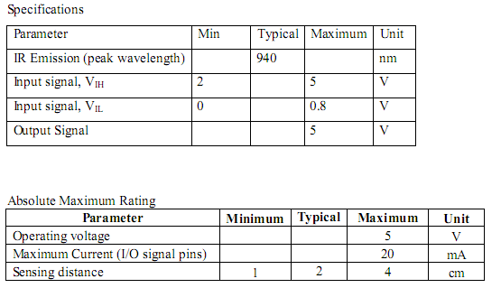
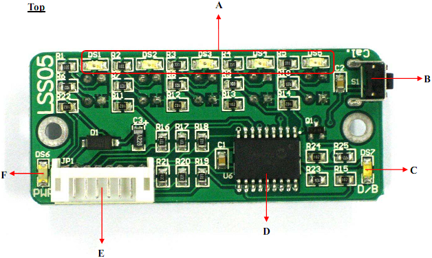
 A – Sensor indicator LEDs (red) will light up showing that it detects line.
B – Calibration button is used to enter different modes. Press once to enter the calibration mode. Press twice to set the line sensor bar into dark line following mode and press 3 times to set the line sensor bar into bright line mode.
C – Mode indicator LED (orange) is for indication of the mode. LED will light up if LSS05 is in bright line detection mode. Otherwise, it is off.
D – PIC16F819 PIC microcontroller for data processing.
E – Power and output signal connector
F – Power indicator LED (green) showing the board is supplied with power. Maximum input power is 5V.
 A – Pairs of IR sensor which consist IR transmitter and IR receiver.
B – It is reserved for Manufacturing Test Point. Please DO NOT short or connect wire to any of these pins.
C –Input/output signal label showing the Power (5V, GND), output signal pins (O1-O5) and calibration signal (Cal.).LSS05 cable connector
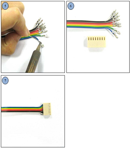
Figure below shown cable used to connect LSS05 to microcontroller. 2020H-08 connector is used at the end of the cable.
 Pin pitch for 2020H connector is not standard size for donut board pin pitch. To use LSS05 with donut board, simply cut the end of connector and solder another type of connector like 2510 or 3960 connector. Following figure is showing the step to connect LSS05 to others type of connector.
 Figure below shown LSS05 was connected to donut board.
 GETTING STARTED
LSS05 need to be calibrated to retrieve the dark and bright value of the surface that it will do the line follow. Every of the IR sensor pairs need to be exposed to the dark and bright surface for it to read the value and save it. LSS05 will save the value in EEPROM, it will retrieve back the data from the EEPROM every time its switch on. Hence, only one time calibration is needed for the same surface and line. To calibrate LSS05, simply press the calibration push button once or pulling down the Cal. for few milliseconds. Calibration will be start by exposing the sensor to the bright surface and then to the dark surface as indicated by the LEDs. 3 LEDs blinking means the bright calibration (2.5 seconds) and 2 LED blinking means the dark calibration (2.5 seconds). Calibration is normally done by crossing every sensor across the line that it will follow as shown in the figure below. Sensors will save the brightest value in the bright calibration process and darkest value in dark calibration. User can calibrate by simply swinging the sensors across the dark and bright surface in order to expose every sensor to the dark and bright surface. Calibration of every sensor is independent and value of each sensor will be saved. Example motions of calibration by crossing the sensor between the lines.1. Calibration button and signal.
The calibration button or the calibration signal (Cal.) has 2 functions. The 1st function is to call for calibration of the line sensor and the 2nd function is to set whether the sensor bar will operate for dark line following or bright line following.2. Using the calibration push button
Press the push button once to set the sensor bar into calibration mode. LSS05 will go into calibration mode and the red LEDs will start blinking accordingly to indicate whether it is calibrating for dark color or bright color.
Press the push button twice will set the line sensor into dark line following mode which LSS05 will detect dark line. Sensor indicator LEDs will light up if it detects dark surface (the line is dark).
Press the push button 3 times will set the line sensor bar into bright line following mode which LSS05 will detect bright line; sensor indicator LEDs will light up if it detects bright surface (the line is bright). Dark/Bright indicator (D/B) indicator LED will light up in orange color for this mode.
3. Using the calibration signal
The calibration signal from the sensor connector can be used to perform exactly the same function as the calibration push button. The calibration signal line requires user to generate falling edges to set for appropriate mode. LSS05 detect how many falling edges to set to appropriate mode.
• One falling edge pulse for calibration mode as shown in figure below. After the falling edge pulse the sensor will start calibration. • Two falling edges for setting the LSS05 into dark line mode. The 2 falling edges need to be in range of 1.5 seconds.
 • 3 falling edges for setting the LSS05 into dark line mode. The 3 falling edges need to
be in range of 1.5 seconds. *Reminder: Please keep the Cal. signal at high logic level 5V if it’s not generating pulse for the function of the signal.


No comments:
Post a Comment